I am attempting to make an RTS based on AoE II HD Edition. I want to have ease of control by designing a transformation matrix given any style of projection I want. This is a good example of what I mean. So, given each of those three angles, and any absolute x, y, and z, how can I design a transformation matrix to multiply the absolute position by to get the projected position on the screen? I just want full control, and I need to get better at matrices. I am about to graduate High School but I hardly learned anything related to matrices. Only a little in Physics and a little in Algebra II with Trig.
I just need to know how to create the matrix.
Also, after that, how would I convert a projected matrix back to the original position? Dividing it (Although, I know matrices can't divide - I mean multiply by the inverse)? Thanks so much for any help!
Answer
I'm going to make some assumptions...
Your 3D world coordinate system is left-handed, with the y axis pointing up in the world.
You want to convert to camera space, where y is up on the screen, x is rightward on the screen, and z points into the screen. (From here projecting into normalized device coordinates is straightforward, so I'll skip that here so we can ignore things like aspect ratios and near/far planes)
The world y axis will point directly up in the image plane and will be scaled by
scaleYthe world x axis will project to point in a direction
angleXradians counter-clockwise from the projected y axis, and will be scaled byscaleXthe world z axis will project to point in a direction
angleZradians counter-clockwise from the projected x axis, and will be scaled byscaleZyour matrix multiplication convention is
M * v(ie. your vectors are treated as columns, multiplied on the right side of the matrix)
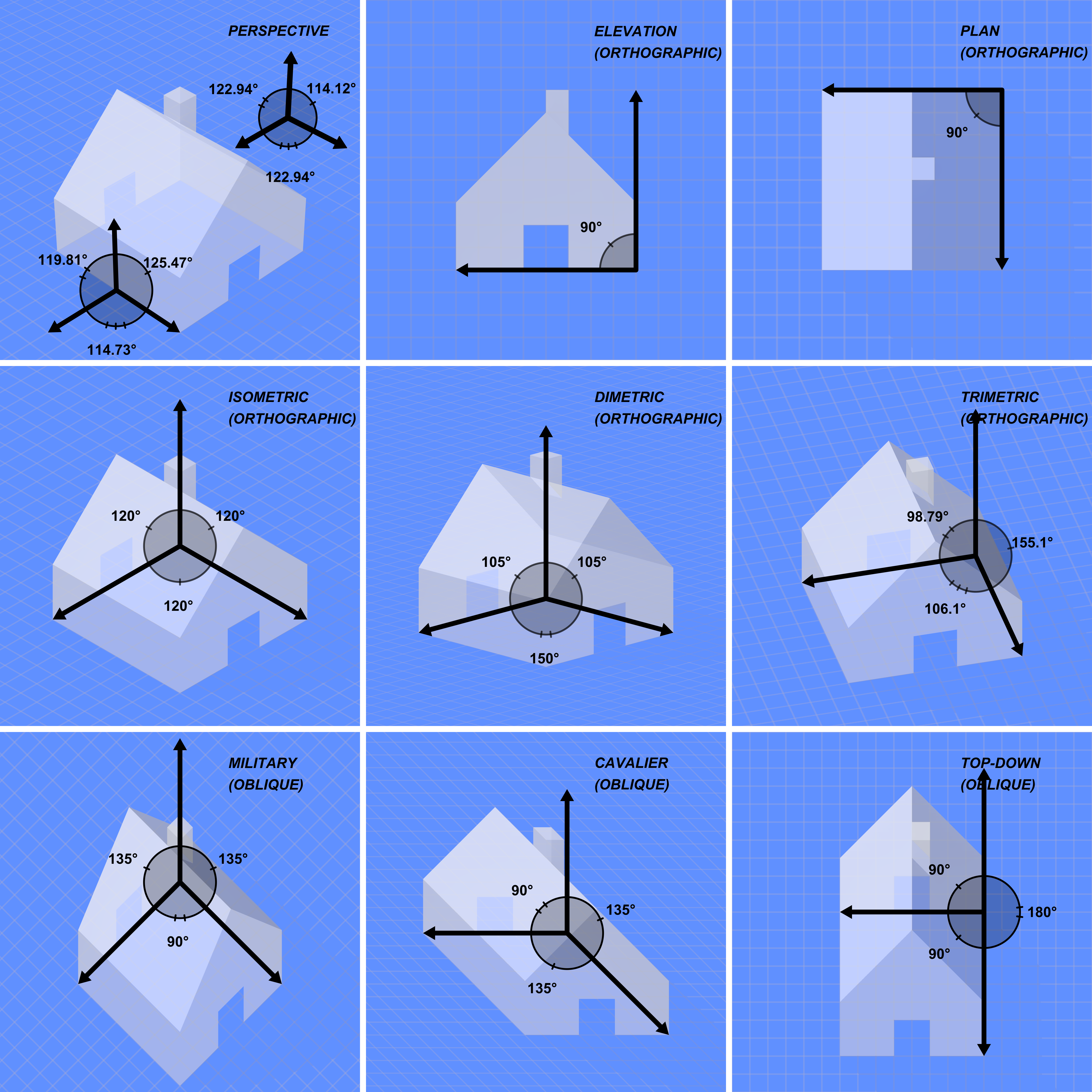
Using these assumptions, we can form various common projections:
- true isometric:
{angleX&Z = 2pi/3, scaleX&Y&Z = 1} - 2:1 dimetric
{angleX = atan(1/2) + pi/2, angleZ = 2* atan(2), scaleX&Z = sqrt(5)/2, scaleY = 1}(this projection is often called "isometric" in games, although it's not quite) - cavalier-45
{angleX = pi/2, angleZ = 3pi/4, scaleX&Y&Z = 1} - plan
{angleX = pi/2, angleZ = pi/2, scaleX&Z = 1, scaleY = 0} - x-elevation
{angleX = pi/2, scaleX&Y = 1, scaleZ = 0}
So with that in hand, we can use some handy facts about matrices. In general transformation matrices we use look like this:
 ┌                ┐
 | Xx  Yx  Zx  tx |
 | Xy  Yy  Zy  ty |
 | Xz  Yz  Zz  tz |
 |  0   0   0   1 |
 └                ┘
Here, the 3x3 block in the top-left represents the rotation, scale (including reflection) and skew applied to the 3D space - the linear components of the transformation.
The right-hand column represents the "affine" component, a translation vector (tx, ty, tz) representing how far the origin of the space is shifted.
And that bottom row (0, 0, 0, 1) lets us use homogeneous coordinates to accomplish the affine transformation above (otherwise we're limited to just the linear component). Often though, we'll just treat this as a given and not really store that row - we'll just multiply "as though" it's there. ;)
We can get more granular in that 3x3 block too. The left-most column (Xx, Xy, Xz) is exactly the direction & scale that will be applied to the unit vector along the x+ axis, (1, 0, 0) (and any vector parallel to it). The same goes for the middle column and the y+ axis, and for the remaining column and the z+ axis.
(This works for the multiplication convention v * M too, just exchange "columns" for "rows" above)
So, knowing this, if we figure out where we want each original axis to point in our image, we can assemble these three vectors to form our rotation/projection. Then we can adjust the translation to center whichever part of the image we want.
First, we'll construct the 2D image of the x+ unit vector (1, 0, 0) and z+ (0, 0, 1) after transforming to image space:
Vector2 xImage = Vector2(-sin(angleX), cos(angleX)) * scaleX;


Vector2 zImage = Vector2(-sin(angleX + angleZ), cos(angleX + angleZ)) * scaleZ;
This is just using the unit circle and basic trigonometry. The image of the y+ unit vector gets scaled to (0, scaleY, 0) according to the assumptions above.
And assuming we want some worldspace vector lookPoint to map to the center of the screen, we'll want to compute a pair of centering offsets...
float tx = -lookPoint.x * imageX.x - lookPoint.z * imageZ.x;
float ty = -lookPoint.y * imageX.y - scaleY * lookPoint.y - lookPoint.z * imageZ.y;
we can form a projection matrix:
                       ┌                                    ┐
Matrix4x4 projection = | imageX.x    0      imageZ.x   tx   |

                       | imageX.y  scaleY   imageZ.y   ty   |
                       |    0        0         0        0   |
                       |    0        0         0        1   |
                       └                                    ┘
This matrix isn't invertible, because we've flattened the z axis to zero. But it's also 2AM here and my faith in my math skills is faltering. ;) So, I'll come back and edit this answer to discuss how we extend this projection to have a sensible z vector so we can reverse the transformation a little later. Hopefully this is enough to get you started. :)
Edit: I still don't have a complete solution to offer, but I wanted to give some explanation of why it's a bit more complicated than it might appear.
If we only wanted to represent orthographic projections, we'd have an easier time. Each image vector would retain its original length, pointing in or out of the image plane to achieve the needed foreshortening, and the view direction (the z-axis of the camera space) would point perpendicular to the image plane in our original coordinate system.
But many of the projections we can form with the parameters above are not orthographic, like cavalier projections. These stretch & squash the axes to arbitrary lengths, which is equivalent to skewing the coordinate system - so the view direction runs diagonal to the image plane.
We actually have some wiggle room in how we choose which diagonal to use, which can impact how we sort objects like sprites that we might be rendering. So, it's important to pick a good diagonal - and that's where things get a bit tricky.
The basic idea is to find a linear combination of our image-space axes that sums to zero. ie.
a * xImage + b * (0, scaleY) + c * zImage = 0
That's a system of linear equations with two equations and three unknowns, meaning it's under-determined. But we can arbitrarily choose some solution where a, b, and c are not all equal to zero, and normalize that into a vector:
n = (a, b, c)/sqrt(a*a + b*b + c*c)
Then our z+ axis can be either n or -n (one will render our scene as desired, the other will flip it backwards - we should be able to tell which one to use based on the angles between the axes in our image, but I haven't worked that bit out yet)
Once we finally have this, we can write our matrix as:
float tz = focalDepth - dot(n, lookPoint);


                       ┌                                   ┐
Matrix4x4 Invertible = | imageX.x    0      imageZ.x  tx   |
                       | imageX.y  scaleY   imageZ.y  ty   |
                       |    n.x      n.y       n.z    tz   |
                       |    0        0         0       1   |
                       └                                   ┘
Where focalDepth is the depth you want your lookPoint to sit at (generally you'll want this to be some distance in front of the camera so you can still render objects that are in front of what you're looking at)
This matrix is invertible, so you can use this to both map from worldspace to camera space, and back to worldspace.
No comments:
Post a Comment